Documentation for the Simulation Editor
of the FRAMEwork System (FRAMES)
Title Page
Legal Notice
Table of Contents
Introduction
Requirements
Design
Quality Assurance and Testing
Design of the Simulation Editor
The FRAMEwork System (FRAMES) includes a suite of editors designed to manage, view, and set up its underlying infrastructure on a single system as well as run a simulation. A full description of the design parameters can be found in Whelan et al. 2002, PNWD-3145.
This section describes the design of the Simulation Editor. Related design information on the other editors can be found in
- Design of the Conversion Editor
- Design of the Dictionary Editor
- Design of the Module Editor
- Design of the Domain Editor.
Simulation Editor General Design
The design of the Simulation Editor is simple but powerful. The user interface design was derived from two previous software systems. One was STELLA, a simulation software package that allows the user to diagram the relationships between variables using equations. The variables were represented by boxes. FRAMES took this concept of representing simple variables and expanded it to allow the representation of complex models that produce data which are consumed by other modules. Instead of simple equations defining the relationships, complex solutions to a complex set of equations can be represented.
The other software package that inspired the Simulation Editor was WebCoros. FRAMES took the WebCoros concept of displaying the status of each module to communicate to the user that computations were progressing.
The FRAMES 2.0 Simulation Editor was also designed to generalize the underlying functionality so that the conceptual site model could be used on any software that had a non-cyclic flow to the calculations. For example, FRAMES 2.0 modules can be built to facilitate any process that can be drawn as a diagram of information flow through a system with no cycles. A cycle in this diagram would be a set of objects and the connections between them such that starting at one object allows you to trace back to that object following the flow arrows. Mathematicians call these diagrams Directed Acyclic Graphs (DAGs). FRAMES was designed around DAGs because a DAG has a clear starting point and a clear ending point and can be collapsed into a single serial execution of the connected objects. In a broad sense, what is stored in a FRAMES 2.0 simulation file is the DAG of the modules, models, and schemes the user has chosen. For each object (represented by an icon and a name) the following information is stored:
- Chosen Module: which module to use for the simulation as chosen by the user.
- Module Instance Label: a more intuitive name given by the user.
- Instance Identifier: a unique name given to a module by the Simulation Editor.
- Scheme: which connection configuration was chosen by the user.
- Consumers: list of modules that consume the results of the chosen module.
- Producers: list of modules that produce results consumed by the chosen module.
Additional detail on information storage can be found in the following subsections.
Another important addition to the FRAMES 2.0 Simulation Editor was the concept of schemes. A scheme is a way a model can connect to other models. For example, if an aquifer chemical transport model can consume a chemical concentration contour in some cases and a chemical flux into the aquifer in others, then two different schemes for the same model need to be defined. In the first case, the module developer would specify that the model consumes the "ChemicalConcentrationContour" dataset and in the other it consumes the "ChemicalFlux" dataset. This scheme listing mechanism allows the Simulation Editor to help the user choose modules that can fit the defined producer/consumer relationships. The table below provides an example scheme for three models.
| Model | Scheme | Produces | Consumes |
| X | Static Boundary | A | |
| X | Typical | A | B |
| Y | Static Boundary | B | |
| Y | Typical | B | B |
| Z | Typical | C | A |
The set of schemes and models shown in the table allow for a large number of diagrams. A simple notation provides a text representation of diagrams:
For example, X1-A1>Z1 states that the first instance of X produced the first instance of A, which is consumed by the first instance of Z. A set of such connections represents a diagram:
Y1-B1>Y2
Y2-B2>X1
X1-A1>Z1
Connection 1 uses the "Static Boundary" scheme of model Y, whereas connection 2 uses the "Typical" scheme of model Y. This module set also implies that a connection like Z1-B1>Y1 should not be allowed because there is no scheme where Z produces dataset B.
Another important feature of the Simulation Editor is the visualization of results. Take the simple three connection graph as an example. It is very beneficial to the user if datasets B1, B2, A1, and C1 (produced by Z1) can be visually inspected. Viewers for datasets are just like those for modules, with a couple of exceptions. First, the viewers do not need to be a permanent part of the diagram as long as they are convenient to use. Second, the viewers do not typically produce a dataset that is recognized by other software. For example, a viewer may invoke Microsoft's Excel and produce a chart in a .xls file. The .xls file is probably not going to be consumed by another module. If a viewer does produce results that can be consumed by another module, that viewer can be labeled and used as a module.
Simulation Editor Input Design
The Simulation Editor is meant to be an intuitive interface for the interaction with the CSM diagram. The user can add modules, connect modules, populate input for modules, and run simulations. What modules are available are defined by the Framework Development Editor (FDE). The FDE is the tool that configures the domain of simulations that the Simulation Editor will allow the user to create. Another way to think about it is the CSM workshop could be used for simulations of chemical movement in the environment or for gravitational forces between bodies in space. The user would not be helped if all the modules for the gravity simulator and chemical transport where lumped together. The two problems can both be modeled in simulations but in different domains. The FDE facilitates the creation and maintenance of those domains. The Simulation Editor uses the currently selected domain to aid the user in diagram development and simulation.
In FRAMES 1.X it was often required that the user connect some module to nearly all other modules. A good example was the Chemical Property Database. This database provided a dataset that contained all chemical properties needed for the models. The problem was that every model in the diagram needed to consume that dataset, and therefore the user was required to connect that single module to all other modules. In FRAMES 2.0, the Simulation Editor includes an additional panel to the top right of the screen. This panel is a global module area. Any module dropped in this area has its output made available to all other modules in the diagram. Thus, the global module panel provides a shortcut to connecting a single module to all other modules. This feature can be overridden by simply adding another module to the main diagram and connecting to other models specifically.
To connect modules, the user simply holds down the "shift" key while using the mouse to drag from one module to another. To disconnect, the user performs the same operation again. Modules are added by highlighting a panel to select it (highlighted in green) and double clicking the selected icon in the module pallette. Modules can be moved to a specific location in the selected area by dragging them with the mouse. Note that there is no meaning to the location of the modules except that it may convey flow better to start at the top left of the area and continue toward the right and down. However, the Simulation Editor does not require or enforce this convention.
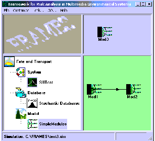
The figure below shows the FRAMES 2.0 user interface. This is the starting point for drawing a CSM. The four areas (Logo, Module Pallette, Global Module Area, and the Scenario Area) can be adjusted by dragging the bar that separates them. The domain in this example is simple: It contains SimpleModules, Stochastic Databases, and the SUTest module. In the Scenario Area, "Mod1" produces results for "Mod2" and in the "Global Module Area" Mod3 produces results that can be used by any module in the "Scenario Area".
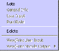
A right-click on any module in the Scenario Area or the Global Area will pop up a menu of actions that can be taken for that module. The figure below shows an example of this menu. The options are identical to the FRAMES 1.3 User Interface except that the new General Info screen has scheme choice added. A description of the General Info, User Input, Run Model, Delete, View/Print User Input, and View/Print Model Output can be found in the FRAMES 1.3 User Interface document.
The Note option is new. This option allows the user to associate a note with a particular instance of a module. When this option is chosen, a dialog with an area for entering text is provided for user input.
Specifications for Simulation Files
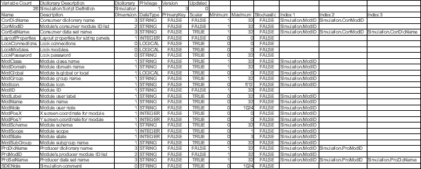
The *.sim file is designed to follow the FRAMES 2.0 dataset dictionary specification. The entries for the .sim file are shown in the following figure.
Several items in this file may require description:
- Lock parameters are used to lock different pieces of a simulation. Currently this functionality is not implemented but the variables are there for future use.
- Layout properties controls sizing of panels.
- SDENote is a string that stores a note about the simulation.
The groups of most interest to the Simulation Editor are the parameters starting with Con, Pro, and Mod. The Con parameters define the consumer relationships for a particular module. ConModId is the list of identifiers for modules from which a particular module can consume results. ConDicName is the name of the dictionary associated with that consumption. ConSetName is the name of the dataset associated with that consumption. The Pro parameters are analogous values for items related to producing results.
The Mod parameters can be divided into user interface parameters and module classification parameters. ModPosX, ModPosY, ModLabel, ModIcon, ModNote, ModGlobal, and ModState represent information the user interface needs to render the module on the screen. Most of the other parameters (ModDomain, ModClass, ModGroup, ModSubGroup, ModName, ModScheme, and ModScope) define placement of a particular module in the hierarchy of modules in the current domain. The most important parameter in the .sim file is ModId. This parameter, together with the Con parameters and the Pro parameters, is used to connect modules. ModId is also used to bind the instance of a module in the hierarchy of the modeling domain.
Specifications for the Startup File
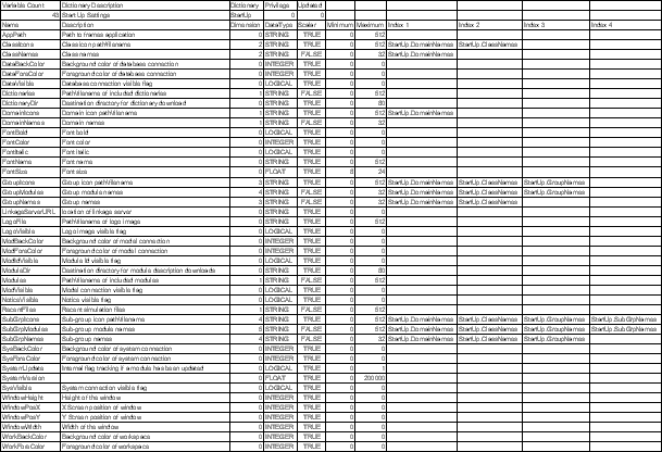
The Startup file (.ini file) also follows the FRAMES 2.0 dataset dictionary specification. The following figure shows the entries for the .ini file. Most of the parameters in this dictionary give the FRAMES 2.0 User Interface flexibility in font, presentation of a logo, and color. These parameters are important but mainly influence the way the Simulation Editor draws the CSM or configures the screen.
The parameters that actually change the capabilities of the Simulation Editor are the parameters that begin with Startup. Other important parameters include DomainNames as index 1, and DomainNames because this set of parameters forms a hierarchy of the modeling domain that the Simulation Editor will present to the user. For example, a domain to model chemical release, transport, and impacts would probably be separate from a domain to model traffic in a transportation system. The hierarchy starts with DomainNames, a list of strings that represents the different domains available. Each DomainName can have a unique icon. Within domains are classes. ClassName is a list of classes within a domain. Each class has an icon and a set of groups associated with it and subgroups within that. GroupNames and SubGroupNames each can have a unique icon.
Only at the level of GroupNames and SubGroupNames can modules be assigned. This feature has the effect of not letting the user drop a module icon for the domain or class. They can, however, drop a module icon for the group or subgroup if a module has been defined.
This organization of modules allows a framework developer to create and organize a set of tools for use with FRAMES 2.0 that will facilitate proper use of the set of modules. Different domains can be recognized and work separately or together with less confusion about available tools.


