![]() Appendix A
Appendix A
A.1 Data Dictionary
A.2 Sensitivity Uncertainty
A.3 Model Considerations
A.4 Editors
A.5 Server Side
A.5 SERVER SIDE OF THE CCEF
Previous design considerations have dealt with the client (i.e., host) side of the CCEF design. The server side of the design addresses models, databases, and frameworks that may be located at remote locations. This section will briefly discuss how databases are dealt with within the CCEF, and it will also present the interrelationships between the host computer and the server side of the design, and interactions with Geographical Information Systems.A.5.1 Databases
Databases represent repositories of information that provide data to populate models within the system. Databases can:- Vary in size. Some databases are very large, but the user may only require access to a small portion of the information
- Be developed for specific models (e.g., aquifer) or applications (micro-environmental)
- Contain special information (e.g., statistical data)
- Be incomplete
- Be located on the host computer or at a remote location.
Based on the CCEF design describing data transfer protocol (i.e., use of Data Dictionary Files), the linkage of databases to other components in the system can be addressed in a similar manner to the linkage protocol associated with models. The model owner defines input requirements for the model through a series of Data Dictionary Files: Input and boundary condition Data Dictionary Files, of which the boundary condition Data Dictionary Files could be defined by upstream models and/or upstream databases. The boundary condition Data Dictionary Files provide the database owner with a template of the data needs of the models in the system and can map the data to the needs of the models.
Because the database owner understands the database structure better than anyone else, it is most appropriate for the database owner to perform the mapping. To avoid a "data dump," the initial mapping would be based on "Primary Keys" that only provide the most appropriate information for selection by the model. Examples of Primary Keys include chemical and organism. The CCEF system would provide the database owner with the necessary tools to map the database contents to the input requirements of the CCEF models, as identified by Database Data Dictionary Files. Therefore, by knowing the BC requirements of the models, Database Data Dictionary Files can be developed and the models would then have the option to consume only that information from the database that met the models needs. A database would populate a dataset meeting the format specifications of a Database Data Dictionary File. To consume that information, the model would reference the same datasets (based on the Database Data Dictionary Files). Data would then be directly transferred from the database to the model.
In the instance where the boundary condition Data Dictionary File is describing a calculated result being transferred from one model to the next model (i.e., Model Dictionary File), there is an expectation that the dataset for that Data Dictionary File or set of Data Dictionary Files will be complete. In the instance where the boundary condition Data Dictionary File is describing information coming from a database, the expectation of completeness is not imposed. It is unrealistic to require a database to understand and meet the input requirements of every possible model that might want to access its data repository. The module receiving information from a database must have provisions to accept incomplete datasets. This means that a default procedure for completing an incomplete dataset must be performed by the receiving model, or a user-interface option (i.e., user intervention) to fully populate the dataset must be provided.
Like models, 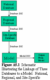 databases could be linked to databases, thereby providing a simple mechanism to prioritize the same type of data (e.g., bulk density) from multiple databases. Figure A5.1 illustrates the linkage of three databases to a model: National, Regional, and Site-Specific. In this example, the databases closest to the model take precedence over those databases farther from the model. If a Site-Specific database did not fulfill the boundary condition requirements of the model, then data gaps would be filled by the Regional database, then the National database. For conflicting information (e.g., different cancer potency factors provided by each database), the closest database could take precedence.
A.5.2 Software Linkage Tools
Software linkage tools allow for communication between host (i.e., local) and remote systems (i.e., running models remotely or accessing data from remote databases). The relationships between Linkage and Module Servers, Host Client, and Remote Databases and Models are presented in Figure A5.2.1.
Figure A5.2.1 CCEF Design Relationships between Linkage and Model Servers, Host Client, and Remote Databases and Models
An explanation of Figure A5.2.1 as it relates to the components comprising the server side of the CCEF design is as follows.
- Data Owner Tool - The Data Owner Tool is support software that allows the Data Owner to map the database structure to a file on the Module Server, which holds the developed extraction plans (mappings), database schema, and the schema of the Database Data Dictionary File. In effect, the Data Owner Tool documents the meta-information associated with the database and data to be extracted, when the extraction is invoked. The Data Owner Tool has already been developed and represents system (i.e., universal) software that needs to be installed and used by the Data Owner. Figure
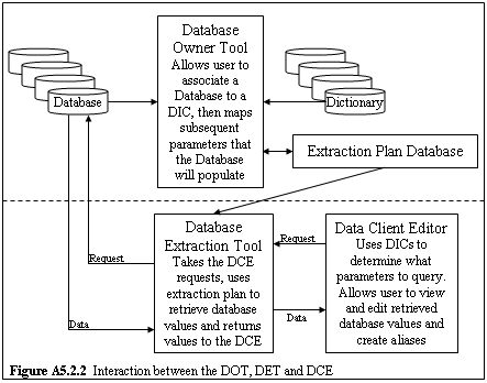 A5.2.2 presents a graphical explanation of the relationship between the Data Owner Tool, Data Extraction Tool, and Data Client Editor.
- Data Extraction Tool - Data Extraction Tool extracts the data from the designated database and returns it to the Data Client Editor through the Hypertext Transfer Protocol (http). When invoked by the Data Client Editor, the Data Extraction Tool goes out to the Data Owner Tool database, retrieves the desired extraction plan from the Data Owner Tool database, extracts the appropriate data through a Structured Query Language server, and returns it to the Data Client Editor. The Data Client Editor then stores these data on the local drive in a designated file for eventual consumption by module icons (and their underlying models) connected to the data-set icon. The Data Extraction Tool has already been developed and represents system (i.e., universal) software. Figure A5.2.2 presents a graphically explanation of the relationship between the Data Owner Tool, Data Extraction Tool, and Data Client Editor.
- Data Client Editor - The Data Client Editor invokes the Data Extraction Tool, which extracts the data from the designated database and returns it to the Data Client Editor through the Hypertext Transfer Protocol (http), meeting the metadata requirements outlined by the Database Data Dictionary File, containing the appropriate Variable Referencing Keys. Only those data associated with the Variable Referencing Keys are extracted from the database. When invoked by the Data Client Editor, the Data Extraction Tool goes out to the Data Owner Tool database, retrieves the desired extraction plan, extracts the appropriate data from the database through a Structured Query Language server, and returns it to the Data Client Editor. The Data Client Editor then stores these data, meeting the specifications of the Database Data Dictionary File, on the local drive for eventual consumption by module icons (and their underlying models) connected to the data-set icon. A Data Client Editor is associated with one data-set icon. Aside from system Data Client Editors, each Database Data Dictionary File is associated with one Data Client Editor, although a Data Client Editor may have multiple Database Data Dictionary Files associated with it. Likewise, multiple Datasets may be associated with a Database Data Dictionary File. For example, for two distinct vadose zones, there will exist two distinct Datasets following the same metadata specifications outlined by a vadose zone Database Data Dictionary File. Likewise, a database (i.e., Data Client Editor) may contain information to populate files corresponding to vadose zone and aquifer Database Data Dictionary Files. Also, multiple databases may populate a Dataset, meeting the format specifications of multiple Database Data Dictionary Files. For example, the Data Client Editor is a user interface that can view and edit the data. The Model Owner is responsible for developing their own Data Client Editor, although the Model Owner can use existing Data Client Editors as a template for their model-specific Data Client Editor. Figure A5.2.2 presents a graphically explanation of the relationship between the Data Owner Tool, Data Extraction Tool, and Data Client Editor.
- Model Owner Tool - The Model Owner Tool is used to define the connections between a Module Server and Remote Model over its Local Area Network, and between the Module Sever and Linkage Server. The Model Owner Tool will pass information, meeting the metadata formats of the Remote Model-specific Input Data Dictionary File and Description Data Dictionary File, from the Remote Model through the Module Server to the Linkage Server. For each new Remote Model being added to the system, the Model Owner Tool will be run, and new files created using the Module Description and Data Dictionary File editors corresponding to the Description and Input Data Dictionary File metadata formats, respectively, will be transferred to the Linkage Server. The Model Owner Tool will most likely be executed by a system analyst, who understands system and Internet protocols. The Model Owner Tool approaches the linkage from the Remote Model and Module Server side, while the Model Execution Tool approaches the linkage from the Client side. For each new Remote Model seeking consideration for inclusion to the system, a new Model Owner Tool needs to be invoked. The Model Owner Tool has already been developed and represents system (i.e., universal) software that needs to be executed by the Remote Model Owner.
- Model Execution Tool - The Model Execution Tool represents a bridge between the Host computer containing the system (i.e., Client) and the Module Server. When coupled with the Model Owner Tool, which has defined the necessary connections to gain access to where the Remote Model is located, the Model Execution Tool can execute request commands from the system, allowing for the direct communication between the System and the Remote Model, so the Remote Model can be run at its remote location. The Model Execution Tool is invoked when linking the Client to the Remote Model with the ability to convert a web-based request to a socket-based request. A portion of the Model Execution Tool software resides on the Host computer, central Module Server (outside the fire wall), and computer where the Remote Model will be executed. The central Module Server coordinates communication with multiple Remote Model locations for that organization. The Module Client (a.k.a., Module Execution Client) resides on the Host computer and includes software that communicates with the Module Server to move files between the Remote Model and Client. The Model Owner Tool approaches the linkage from the Remote Model and Module Server side, while the Model Execution Tool approaches the linkage from the Client side. The Model Execution Tool represents system software, which is automatically executed by the system, when invoked.
- Client to Linkage Server Software - Software is currently under development that will allow for communication between the Client and the Linkage Server. The Linkage Server will contain a listing of all remote models currently available to the Client. The Client has a master list of all currently installed models in the System. The software will be able to identify when models have been removed from service or been updated. This new software will link the Client to the Linkage Server, so the master list on the Client can be compared to the Linkage Server list; at which time, a web page with links to the Remote Model installs associated with the new models can be invoked, if the Client chooses to update the master list of available models. The software will automatically update the master list, if a Remote Model owner removes their model from consideration (e.g., major error in the model, obsolete model, a significantly new version of the software, etc.). Under other circumstances, the user will be asked if an update is required, if a new version of a model or even a new model becomes available for inclusion into the system. Client to Linkage Server Software represents system software, which is automatically executed by the system, when invoked.
- Remote Module Client - The Remote Module Client is a piece of software that allows the Model Owner Tool / Model Execution Tool to setup and execute model runs on remote systems. This software should be written in Java and should be able to run on any platform that supports Java2. It must be installed and executed on all systems on which remote models will be run. All systems running the Remote Module Client will be registered and managed through the Model Owner Tool.
The Data Owner Tool, Data Client Editor, and Data Extraction Tool represent software for accessing remote databases. The Model Owner Tool, Model Execution Tool, and Remote Module Client represent software for accessing and running remote models.
A.5.3 Geographical Information System
Many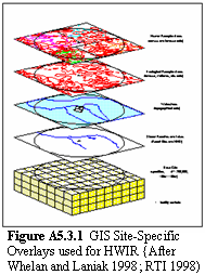 modeling systems are beginning to take advantage of Geographical Information Systems as a powerful support tool to cross-correlate and relate spatial information between models. For example, the 200 sites, which form the underlying foundation of U.S. Environmental Protection Agencys Hazardous Waste identification Rule, are based on data collected with GIS site-specific overlays, as illustrated in Figure A5.3.1. As illustrated in the Hazardous Waste identification Rule example, many programs are moving to Geographical Information System formats to store, access, and correlate spatial data so multiple models are working from consistent data.
Under the design of the CCEF, a graphical user interface will allow the user to:
- Import Geographical Information System data files and incorporate Geographical Information System information into the CCEF, so that all modules can access this information through a single consistent interface.
- Graphically place spatial modeling attributes (e.g., contaminant sources and receptors) on a site base map as part of the conceptual site model development for a modeling scenario
The complete tool will allow decision makers and modelers to easily modify the conceptual site model for a modeling scenario. When the modeling has been completed, the environmental and risk results can then be analyzed to assess the risk implications of changing conceptual site models. The result will be to make this capability more directly accessible to client users and more useful for problems where decision makers disagree or are uncertain about important site parameters. The essential spatial information required to define the conceptual site model is passed, via the Data Dictionary File specifications, containing all spatial modeling data. The Data Dictionary Files have been structured to allow for the model developer to specify those parameters that are spatially aware.
Data are spatially aware when they have been designated as having a Location index, constituting the coordinates of the vertices associated with a polygon (see Table A3.2.1). Clear distinctions have to be made between spatial system data (i.e., spatial layout of components, such as sources and receptors) and non-spatial model data (i.e., porosity, temperature, Kds, toxicity, age, etc.). The spatial data entered through the conceptual site model graphical user interface is divided into three object categories: points, lines, and polygons, all requiring coordinates of their vertices.
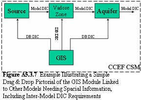
Figure A5.3.2 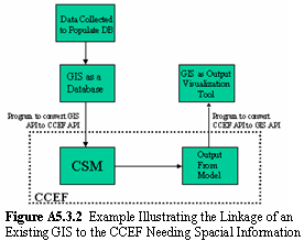 presents an example illustrating the linkage of an existing Geographical Information System to the CCEF. Data are traditionally collected, and the Geographical Information System database is populated with these data. This may be done outside of the assessment process (Figure A5.3.2), as was done with the Hazardous Waste identification Rule assessment, or the user may choose to have the spatial data requirements of the models designated by the user using a conceptual site model Geographical Information System graphical user interface, delivered as part of the conceptual site model (Figures A5.3.3 through A5.3.6, below). Each GIS has its own special file formats [e.g., ESRI Shape files (*.shp), AutoCAD (*.dwg), Drawing Interchange Files (*.dxf), Windows Bitmap (*.bmp), and Tag Image Files (*.tif and *.tff)]; as such a program will link the Application Programming Interface of the Geographical Information System system to that of the CCEF, thereby allowing for the conversion and transfer of data from the Geographical Information System to the CCEF. The CCEF uses the data and may produce spatially aware output results, which could be converted back to the Geographical Information System file formats for visualization as a Geographical Information System viewer (see Figure A5.3.2).
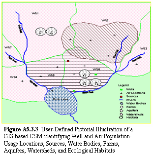
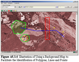
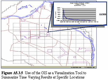
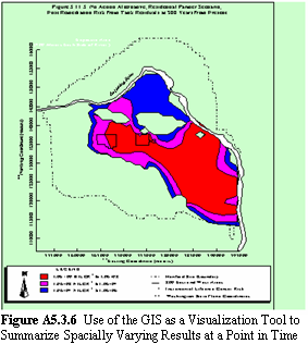
The user does not see the mechanics behind the linkage of the Geographical Information System to the CCEF conceptual site model, as illustrated in Figure A5.3.2 (above). In the users work space (see Figure A5.3.7 below) and from a set of system icons, the user would choose the Geographical Information System icon and connect it to all of those models that require spatial information and expect to receive the spatial data from the Geographical Information System. The user would then link the Geographical Information System icon to those models requiring spatial data, as illustrated by Figure A5.3.7 (below). If the data comes from a standard database, then a Data Client Editor (coupled with a Data Owner Tool and Data Extraction Tool) is used to transfer the data to each model. If the user wants to develop a real-time spatial picture of the conceptual site model, then software would be available to identify the polygons, lines, and points associated with the conceptual site model, as illustrated in Figures A5.3.3 and A5.3.4 (below). Figure A5.3.3 pictorially illustrates a user-defined Geographical Information System -based conceptual site model, identifying well and air population-usage locations, sources, water bodies, farms, aquifers, watersheds, and ecological habitats. Figure A5.3.4 illustrates the use of a background map to facilitate the identification of polygons, lines, and points. Figures A5.3.5 and A5.3.6 illustrate how the Geographical Information System could be used as a visualization tool to inspect time varying at specific locations or spatially varying data at a point in time, respectively.